
Rubber Track Chassis specs get compared by track width and overall length more often than by the number that actually predicts how a platform performs once it leaves the workshop floor: ground pressure. A tracked robot or small utility platform spreads its weight across the full contact length of both tracks rather than four contact points, and that difference is what lets a lighter machine cross soft ground a wheeled equivalent would sink into. Engineers speccing a Rubber Track Chassis for a mission profile that includes mud, loose sand, or tilled soil are usually working backward from a maximum allowable ground pressure figure, then checking whether a given track width and wheelbase combination gets them under it.
That calculation changes depending on what sits on top of the chassis. A Rubber Track Chassis carrying a fixed sensor mast or a manipulator arm shifts its center of mass forward or upward compared to a flat cargo deck, and that shift concentrates load on the front idler and drive sprocket during any incline or sudden stop. Integrators who size a chassis purely against the static payload weight, without accounting for where that payload sits, sometimes end up with a platform that handles fine on a bench test and then digs in at the front on a slope it was rated for on paper.
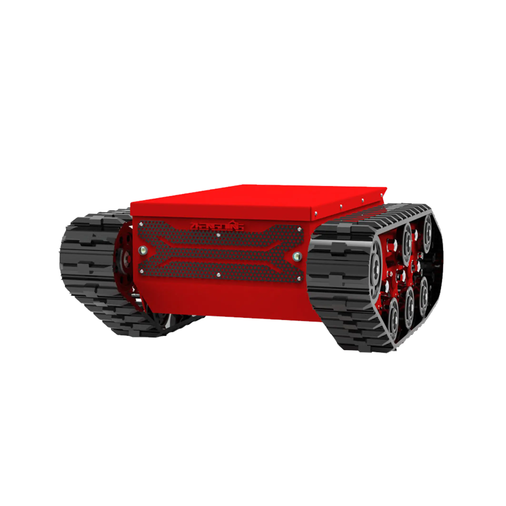
Traction on mixed terrain comes down to lug pattern and pitch, not overall rubber thickness. A tighter lug pattern with shorter pitch keeps more rubber in contact with hard or paved surfaces, which matters for platforms that move between a workshop floor and an outdoor test site in the same shift. Wider, deeper lugs with longer pitch bite into loose or wet ground but transmit more vibration back through the chassis at speed, which is a real concern on a Rubber Track Chassis carrying cameras, lidar, or other sensors that depend on a stable image or point cloud rather than a smoothed-out one.
Tension setup affects a separate part of the Rubber Track Chassis performance envelope: obstacle climbing and how the track behaves under sudden load. A fixed-tension idler setup is simpler to build and service, and it works fine for platforms operating mostly on flat or gently sloped ground. An adjustable or spring-loaded tensioner keeps the track seated against the drive sprocket when the chassis climbs over a curb, a rock, or debris, reducing the chance of the track walking off the sprocket mid-obstacle. Platforms built for inspection or agricultural work, where the ground surface changes constantly, tend to specify the adjustable setup even though it adds a service point technicians have to check.
Drive sprocket engagement is the detail that shows up as a problem only after the chassis is already in the field. A sprocket profile that does not match the track's internal tooth spacing closely enough will slip under sudden torque, usually right when the platform needs traction badly, climbing an incline or pulling free from soft ground. Matching sprocket tooth count and pitch to the specific Rubber Track Chassis being used, rather than assuming any sprocket rated for the same track width will work, is one of the checks integrators tend to skip until a field failure forces the conversation.
None of these variables move independently. A track width chosen to hit a ground pressure target changes the sprocket load, which changes how much tension the idler setup needs to hold under climbing conditions, which then feeds back into how much vibration reaches whatever sensor package sits on the deck. A chassis platform gets specified around a mission profile for exactly this reason, with track, tension system, and drive sprocket sized together rather than picked as separate line items from a catalog.

 Building 1 and 2, No. 2269, Jingzhong Road, Hongjia Street, Taizhou, Zhejiang, China
  +86-18857621312
  info@zinntu.com

 English
 русский
 عربى
عربى
